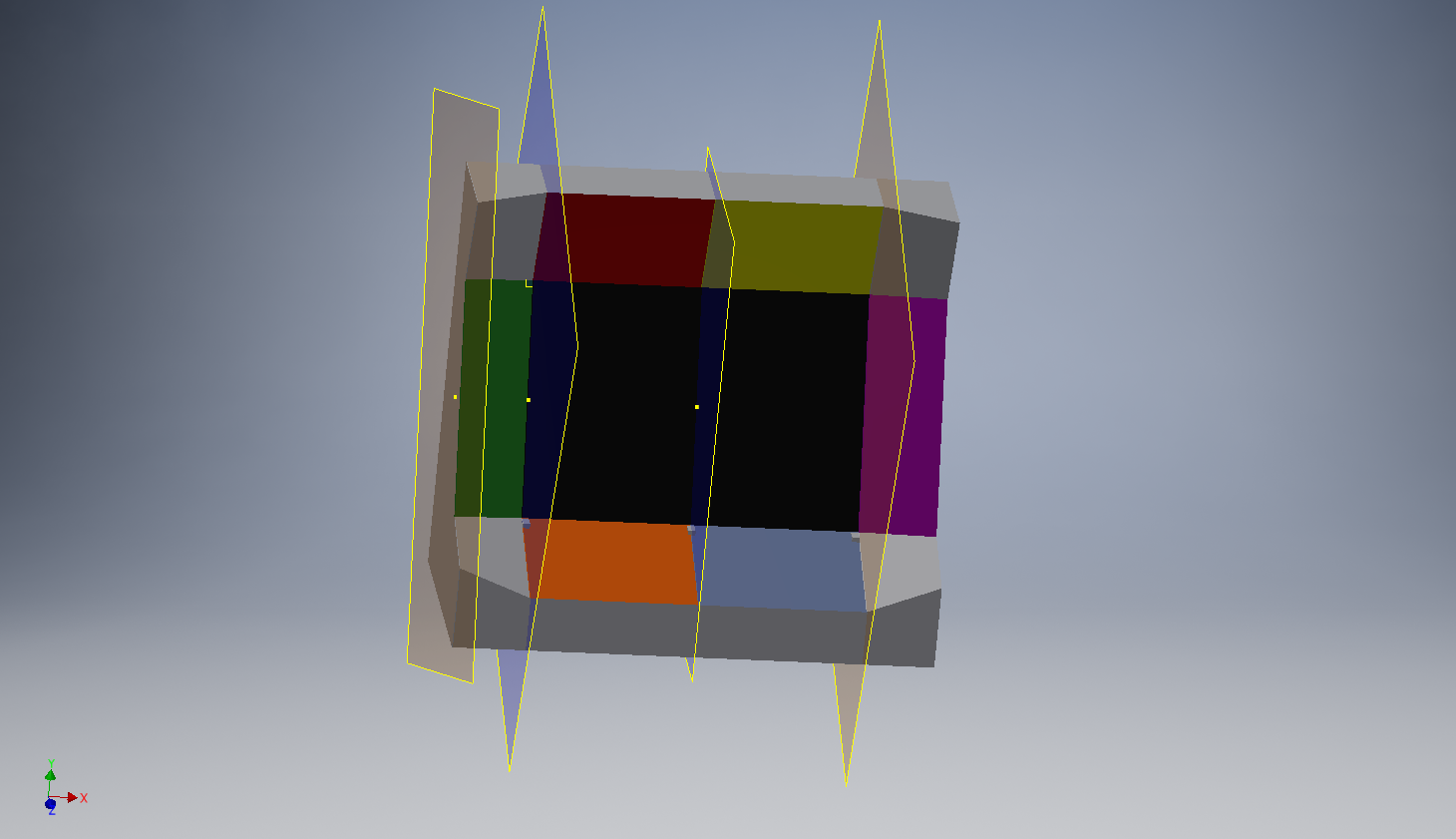
Currently finished coupling 6 legs to a simulation body, with the leg inverse kinematics functional for all of the legs. The remaining elements to implement would be select-able individual joint controls for each leg and the body kinematics itself.
Then I completed the inverse kinematics that allows for the coupling between the body of the robot and its 6 corresponding legs (arranged with 60 degrees between each leg). I won’t bother explaining the mathematics going into these calculations in detail as they have been outlined in Oscar Liang’s blog post and the equations from TogleFritz’s Lair.
The resultant equations needed a bit of tweaking, especially with the orientation of the coordinate plane and the direction of certain rotations. Additionally, the equations from TogleFritz’s Lair are unnecessarily redundant when implemented in code. I added some optimizations and loop logic to help make the equations less cumbersome to use.
The Droid project, is a project where I am attempting to design and build a hexapod robot from scratch. Given, that I have no prior experience dealing with the forward and inverse kinematics problems (FK & IK) that need to be solved, I resolved to using Cinder and ImGUI to create a simulation of the hexapod first.
So far, I am still in the early stages of the project, but I have come up with a simulation for a single leg of the hexapod. With much help from Oscar Liang, and his informative blog series on the kinematics of hexapods, I managed to get the IK for a single leg to work.
Now, the next part would be to get the full body IK to work, and figure out how to implement basic movements. And then we can finally take a look at the hardware we have to work with :’)
This is the post zero in a series of posts about the KSP control station we have been working on for a while now. This project got its beginnings back when we were preparing for Maker Faire Singapore 2016 where we wanted to make something big. Something that people would see from across the room and go "Wow!".
So in the end, we came up with the KerbalKontrol V1.0 which was quite successful and attracted a lot of attention at Maker Faire. In addition, it also got some love from the Reddit and Hackaday community! The response was some of the best we have had since we launched and motivated by that very response we decided to launch this series.
In this series, we will be re-doing the whole project again in a less rushed manner than it was done before and iron out all the quirks and the problems we had before, both software and hardware. We will also be starting a Gitlab repo for this and publicly sharing all our design files with the community so if you are interested in making
The second ever full fledged Maker Faire has made its pass this year and it was a really productive and enriching experience. We as MakerForce did have a booth there and we all had a lot of fun. In this post, I will be talking about the Maker Faire experience in Singapore , our booth and the interesting people we met there.
A photo posted by Another Arch Linux User (@ambrosechua) on
The Maker Culture
I've got to say that the maker culture in Singapore is increasing rapidly. Just 3 years ago, there were just 1 hall full of booths. This year, there was at least 3 halls full of fun and creativity. From pneumatic musical instruments to escape rooms, this year's Maker Faire was overflowing with awesomeness. Also, this year's Maker Faire was held in in the SUTD campus, which gives me a good excuse to check out SUTD as a future university.
Personally, this is my 4th Maker Faire I've been to and the 2nd Maker Faire I've had a b
So it has been a while and I've been using the solder reflow oven for a while now. For the past weeks, I've been experimenting with finer and finer pitch components and I've been having really good progress so far.
The reflow oven performs way better than what I expected as it has fairly even heating through the oven and can solder super fine pitch components. One such example is the edison or hirose 70 pin connector. Despite the 0.5mm pin pitch my reflow oven managed to perfectly reflow the connector countless times.
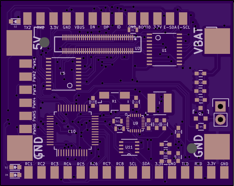
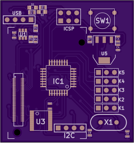
The EdiCopter board is back and its better than ever. The EdiCopter board has seen several revision since I last posted on it but today I'm releasing the second public revision of the EdiCopter Board. It employs the use of SMD components and optimizes the space in the PCB to better use the area and make it smaller.
Improvements
I have made several improvements to the board since last time. One of the more significant changes is the fact that the components are more evenly distributed between the top and bottom of the PCB. There is also proper silkscreen labeling of the PCB.
The size of the PCB has also shrunk by almost half. This makes it easier to mount them on the SentiBot and also allows for us to make the SentiBot smaller.
Solder Reflowing
I will be reflowing this PCB in my new custom reflow oven. I also had bought the OSHStencil stencil for reflowing. I will be posting a follow up talking about how the reflow oven performs soon.
I have been playing Kerbal Space Program on/off for a few years now, ever since the 0.23.5 update. The game came of out of Steam Early Access last year and the recent update 1.1 upgraded the game engine to Unity 5, improving the multi-threading of the physics processing. And so when we were coming up with ideas to do for MakerFaire 2016, I suggested building a custom KSP controller.
There already have been numerous projects done by others in the KSP community. These are documented across the KSP forums, and the KSP subreddit. These mainly involve integrating a joystick into a platform together with a few buttons and switches that are essential to flying a rocket in KSP. Ambrose, however, had not seen these, and designed what is essentially a command station with inspiration from the NASA mission control stations.
The overkill command station is born
The middle section holds a 27 inch monitor, joystick and buttons on the bottom panels, and more switches and lights on the top panel. Eve
In this penultimate installment to the reflow oven project, we will wrap up by quickly going through some basics of the final hardware assembly and the software.
Insulation
Insulation is a important concern when you are building a reflow oven. If poor attention is given to insulation, you might end up reflowing your control electronics along with the other board. I implemented insulation by putting all the sensitive electronics into a cardboard box.
Power
Another important concern is the power for the arduino and the processing board. I implemented that by hacking a 5V 2A power supply and converting 240AV to 5VDC in the toaster. This 5VDC can then be used to power the electronics.
In this second installment of the solder reflow oven series, I'll be going over the electronics that makes it work. The solder reflow oven can be split into 3 main sections.
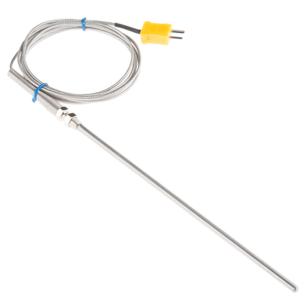
Temperature Detection
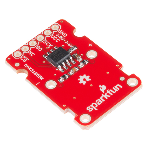
The first section is the temperature detection. The temperature detection at this kind of high temperatures (around 250°C) requires the use of a thermocouple to work. This is because a thermistor doesn't work at high temperatures. The thermocouple I obtained was from SparkFun and was a type K thermocouple. As a typical microcontroller cannot directly read the output of this thermocouple, it is necessary to have an external circuit to process the thermocouple voltages. Fortunately, SparkFun also sells a MAX31855K breakout board which I also grabbed.
Heating Element Control
The second section is the control method. To manipulate the temperature inside the oven, we need to toggle the power to the heating elements. For this,
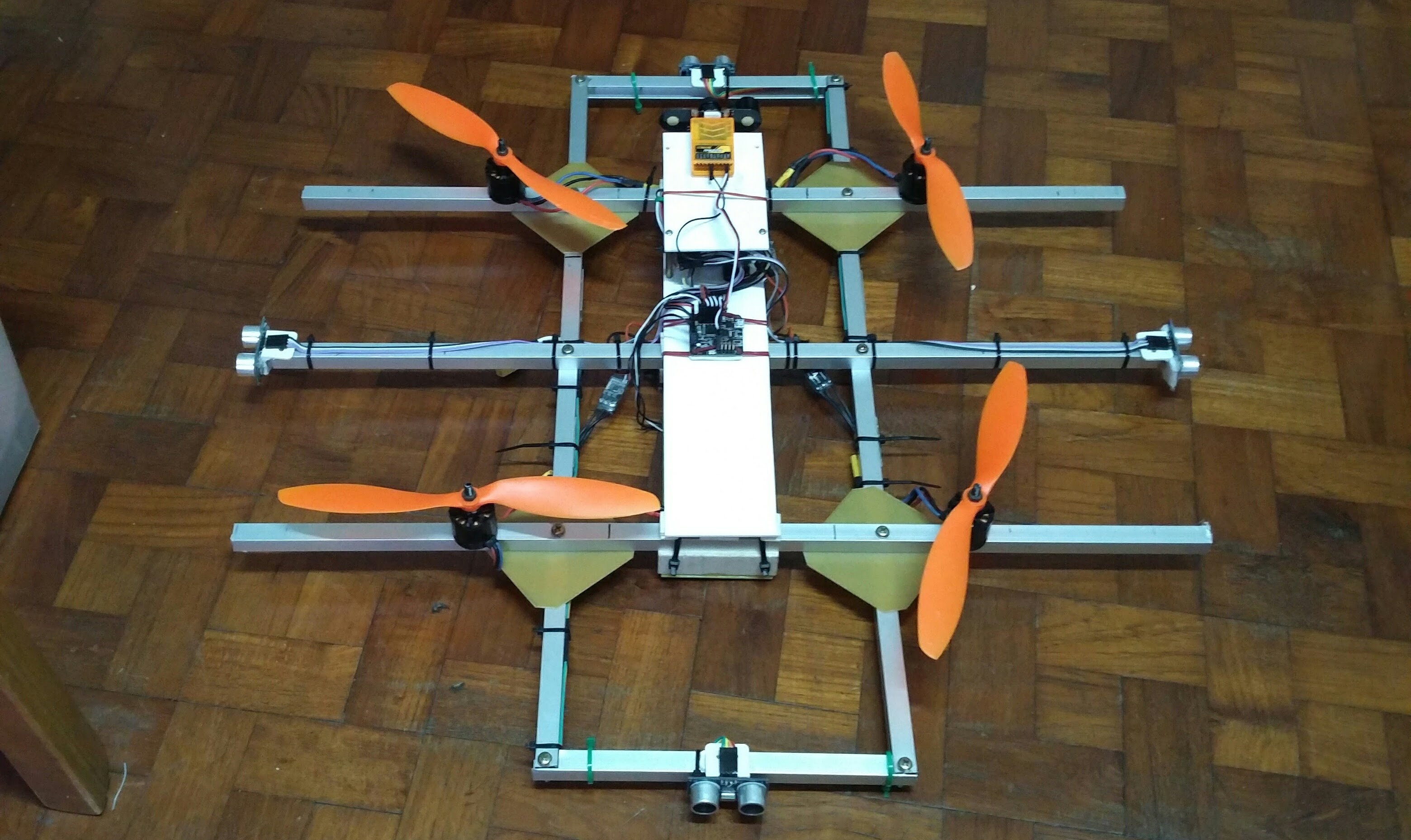
For SAFMC 2016, we built a custom frame to accommodate what we needed. I call it the Tic Tac Toe.
Navigation
Before working on the frame, we first decided on a navigation system. To avoid reinventing the wheel, we chose a Naze32 to provide basic flight stabilization for our quad. It is tried and proven to be reliable, especially with an open source firmware with active development.
Onboard accelerometers and gyros allow the Naze32 to provide stabilization for the quad. It is most often used for RC micro race quads (watch out for a post!). Higher level navigation will mimic an RC input into the Naze32, hence controlling the attitude of the craft.
Working on a budget, we decided to give ultrasonic sensors a try. Data from the sensors is processed by the onboard Pi with a custom algorithm to provide instructions for the Naze32.
Frame
Hence with the navigation system set, we built our frame around that. The concept of the tic tac toe frame came about when we realised it could solve a few
This is it. It has finally been one year since the SentiBot's project launched. This project is older than the existence of MakerForce itself. Let's take a look at some memorable moments from the past year.
This was the first ever prototype model created of SentiBots. It has evolved into a completely different model today.
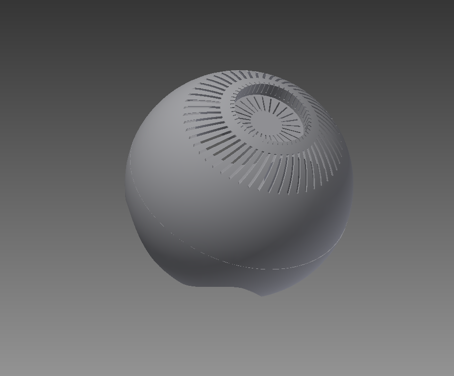
Here is an early snapshot of the EdiPlane PCB created last year. We very quickly realized that a spherical shape is just pointless and makes it hard to mount stuff inside.
Prototype 1- codename Prime.So naturally, we extended into a bean. Also beans are awesome. The battery mounting was still a bit iffy but its an improvement. This model did not fly.
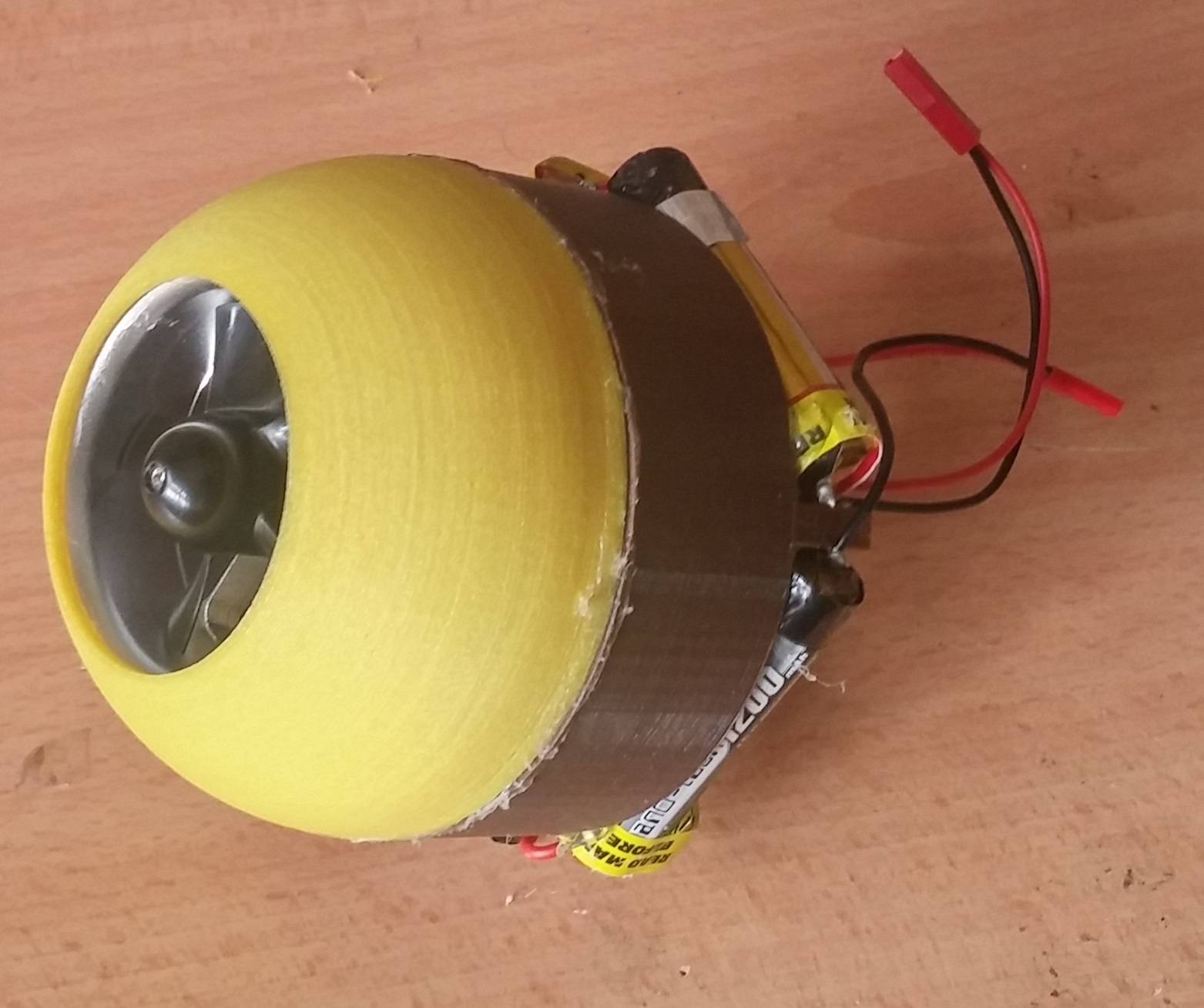
Prototype 2- codename Snow White. Snow white was a very interesting prototype as it is the only SentiBot created to have a nylon frame and its extraordinarily durable. This still uses the single EDF propulsion method.
Prototype 3- codename Sentinel. This was the first SentiBot to have the hump to expand upon the spa
So this will be the first post in a series of me making my own solder reflow oven. As you all know, the number of PCB related posts are increasing steadily with EdiCopter and our custom quadcopter boards on the way. I though that this would be the perfect time to get ourselves a solder reflow oven and maybe start small scale manufacture and went over to a nearby shop and grabbed myself the cheapest toaster money could buy.
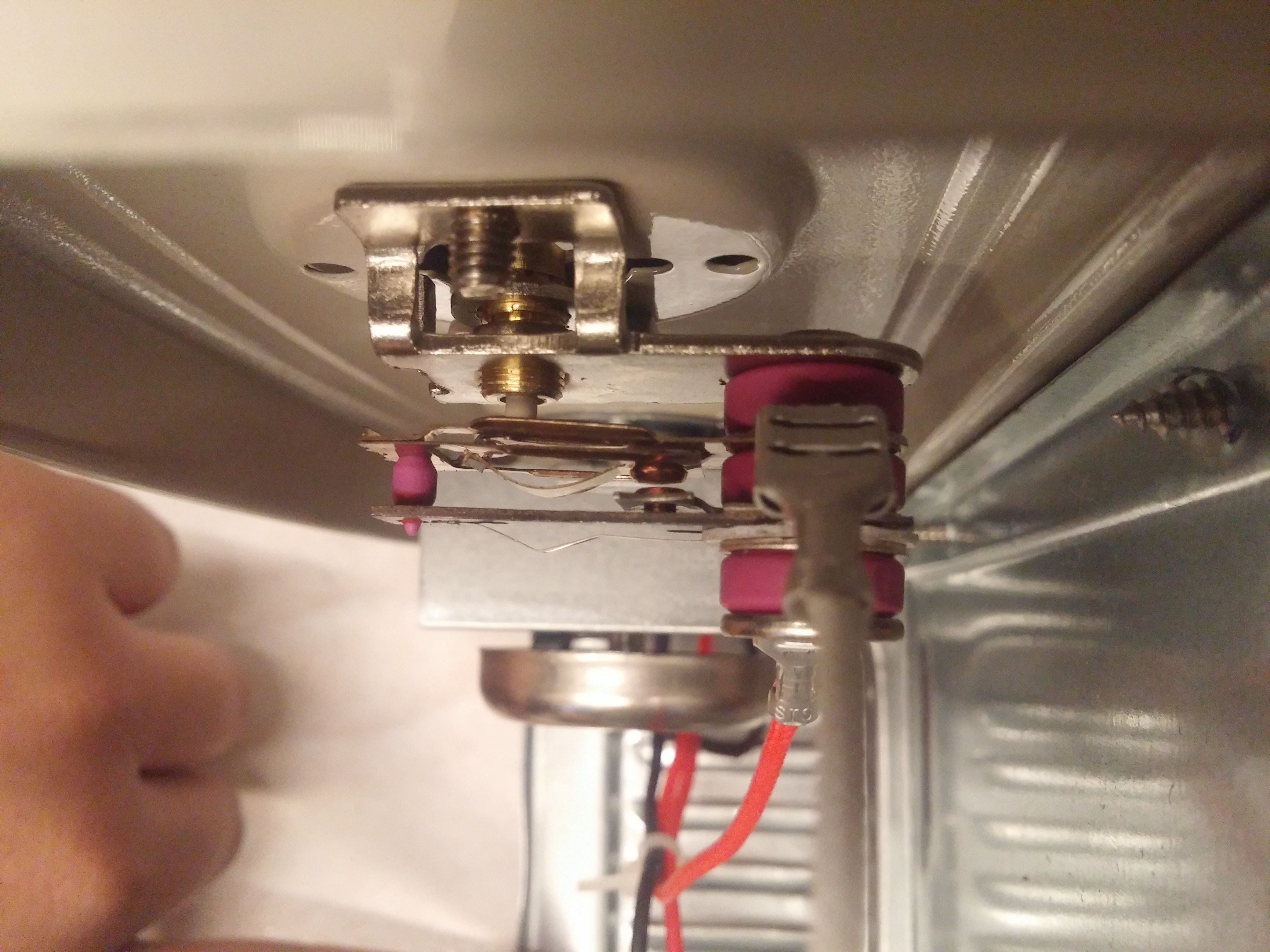
For its price, this toaster's not bad. It comes equipped with a bimetallic strip based thermostat design which is pretty commonplace in toasters these days. When the strip heats up to the right temperature, it bends away from the contact and disconnects the power to the heating element. Pretty neat low-cost mechanism.
It has a nice big cavity inside which will work wonderfully with our extra electronics inside. It looks like with the amount of space we have to work with, we could easily enclose everything within the frame itself making it look as stock as possible