As a kid, I wasn't actually all that into technology. When I was 7/8 years old, the only real things that mattered to me was going to chess club and studying. So I was really surprised when I was introduced to Zubin, a rather inquisitive kid who just wants to tinker.
I was approached to coach Zubin, and help him along with the projects that he would want to make, and I met him for the first time yesterday! The first thing that caught my eye was how his parents had encouraged his maker habit, he had a room with a 3D printer, cardboard boxes, LittleBits, literally anything a 7 year old with maker ambitions might want. On top of that, when I met him, he was working on a 3D printed boat which he was in the middle of designing using TinkerCAD.
My first task with him was to help him finish his boat which came along splendidly. Unfortunately, it took about 4 hours to print it out, and our session was only 2 hours long so we had to come up with a way to keep ourselves busy. I told him that brush
This post is a bit delayed, but Oshstencils, my goto solder stencil supplier, has recently revamped their website along with adding stainless steel stencils!
I was really excited about the new stainless steel stencils option as I have never actualy used stainless steel stencils before and as far as I knew, they were more reliable and durable compared to kapton Polyamide.So of course, I went out and ordered a set of stainless steel stencils for my EdiCopter PCB board. In this post, I will be comparing stainless steel stencils to the classic Kapton polyamide ones.
Benefits
The main benefit of stainless steel over Kapton polyamide is the durability. This can be seen from the rated usage cycle where stainless steel is rated for many times more usage compared to the Kapton polyamide counterpart. Another benefit for me personally is the stiffness which al
Autodesk bought Eagle! If you haven't been living under a rock for the past week, you would have heard the news that Eagle was sold to Autodesk by farnell/element14. How do I feel about it? Well, that's what I'll be talking about in this post.
First reaction
The first reaction I had to this piece of news when I heard it was to think that that was awesome! I'm sure most of you who read my posts know I'm a hardcore Autodesk fan and the fact that Eagle is now run by Autodesk just gave me more reason to move to it (aside from the bountiful libraries). So, in short, I was quite excited about it.
Some time later...
So I gave it more thought as I contemplated switching from my daily driver software KiCad to Eagle. Then Adafruit released this awesome interview with Autodesk about their new purchase. It seemed to indicate that Autodesk will be making incremental updates to the Eagle software. I hope they improve on the UX a bit more and stuff but all that is going to take time.
KiCad vs Autodes
Part 1: Toaster
Part 2: Electronics
Part 3: Software
Part 4: Conclusion
So it has been a while and I've been using the solder reflow oven for a while now. For the past weeks, I've been experimenting with finer and finer pitch components and I've been having really good progress so far.
The reflow oven performs way better than what I expected as it has fairly even heating through the oven and can solder super fine pitch components. One such example is the edison or hirose 70 pin connector. Despite the 0.5mm pin pitch my reflow oven managed to perfectly reflow the connector countless times.
So having said that, I think there are still a few software bugs that plagu
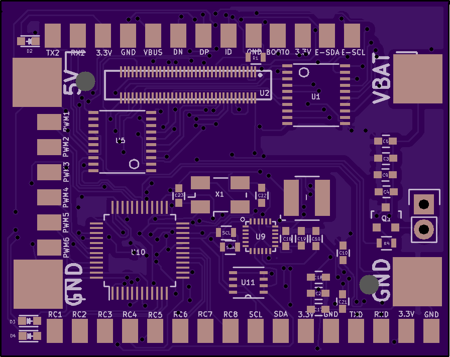
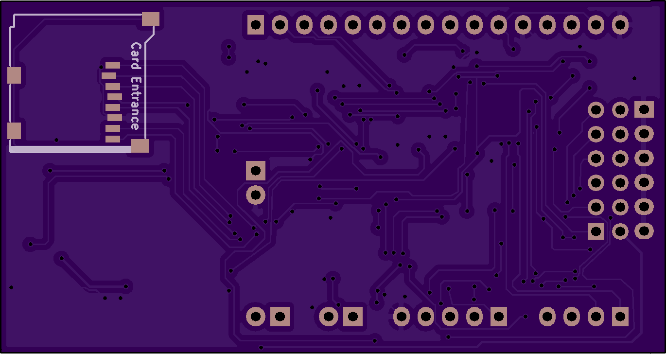
The EdiCopter board is back and its better than ever. The EdiCopter board has seen several revision since I last posted on it but today I'm releasing the second public revision of the EdiCopter Board. It employs the use of SMD components and optimizes the space in the PCB to better use the area and make it smaller.
![]()
Improvements
I have made several improvements to the board since last time. One of the more significant changes is the fact that the components are more evenly distributed between the top and bottom of the PCB. There is also proper silkscreen labeling of the PCB.
The size of the PCB has also shrunk by almost half. This makes it easier to mount them on the SentiBot and also allows for us to make the SentiBot smaller.
Solder Reflowing
I will be reflowing this PCB in my new custom reflow oven. I also had bought the OSHStencil stencil for reflowing. I will be posting a follow up talking about how the reflow oven performs soon.
I have been playing Kerbal Space Program on/off for a few years now, ever since the 0.23.5 update. The game came of out of Steam Early Access last year and the recent update 1.1 upgraded the game engine to Unity 5, improving the multi-threading of the physics processing. And so when we were coming up with ideas to do for MakerFaire 2016, I suggested building a custom KSP controller.
There already have been numerous projects done by others in the KSP community. These are documented across the KSP forums, and the KSP subreddit. These mainly involve integrating a joystick into a platform together with a few buttons and switches that are essential to flying a rocket in KSP. Ambrose, however, had not seen these, and designed what is essentially a command station with inspiration from the NASA mission control stations.
The overkill command station is born
The middle section holds a 27 inch monitor, joystick and buttons on the bottom panels, and more switches and lights on the top panel. Eve
Part 1: Toaster
Part 2: Electronics
Part 3: Software
Part 4: Conclusion
In this penultimate installment to the reflow oven project, we will wrap up by quickly going through some basics of the final hardware assembly and the software.
Insulation
Insulation is a important concern when you are building a reflow oven. If poor attention is given to insulation, you might end up reflowing your control electronics along with the other board. I implemented insulation by putting all the sensitive electronics into a cardboard box.
![]()
Power
Another important concern is the power for the arduino and the processing board. I implemented that by hacking a 5V 2A power supply and converting 240AV to 5VDC in the toaster. This 5VDC can then be used to power the electronics.
Software
The software is critical to this project. Every reflow oven goes through 3 main phases. These phase
Part 1: Toaster
Part 2: Electronics
Part 3: Software
Part 4: Conclusion
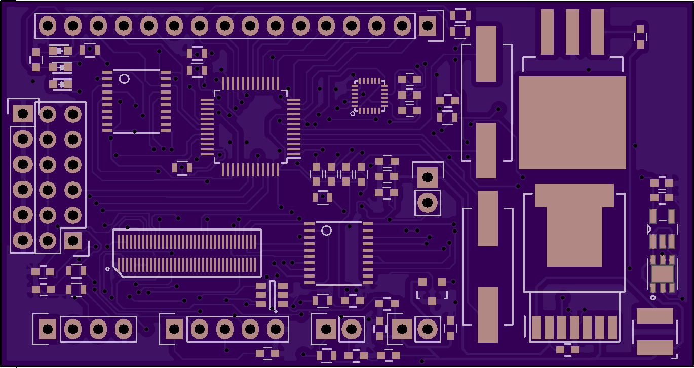
In this second installment of the solder reflow oven series, I'll be going over the electronics that makes it work. The solder reflow oven can be split into 3 main sections.
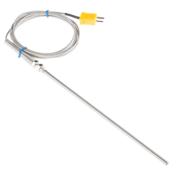
Temperature Detection
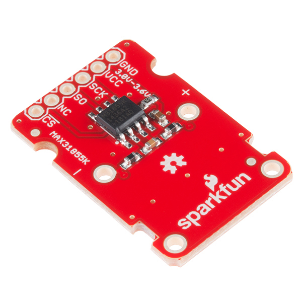
The first section is the temperature detection. The temperature detection at this kind of high temperatures (around 250°C) requires the use of a thermocouple to work. This is because a thermistor doesn't work at high temperatures. The thermocouple I obtained was from SparkFun and was a type K thermocouple. As a typical microcontroller cannot directly read the output of this thermocouple, it is necessary to have an external circuit to process the thermocouple voltages. Fortunately, SparkFun also sells a MAX31855K breakout board which I also grabbed.
Heating Element Control
The second section is the control method. To manipulate the temperature inside the oven, we need to toggle the power to the heating elements. For this,
So this will be the first post in a series of me making my own solder reflow oven. As you all know, the number of PCB related posts are increasing steadily with EdiCopter and our custom quadcopter boards on the way. I though that this would be the perfect time to get ourselves a solder reflow oven and maybe start small scale manufacture and went over to a nearby shop and grabbed myself the cheapest toaster money could buy.
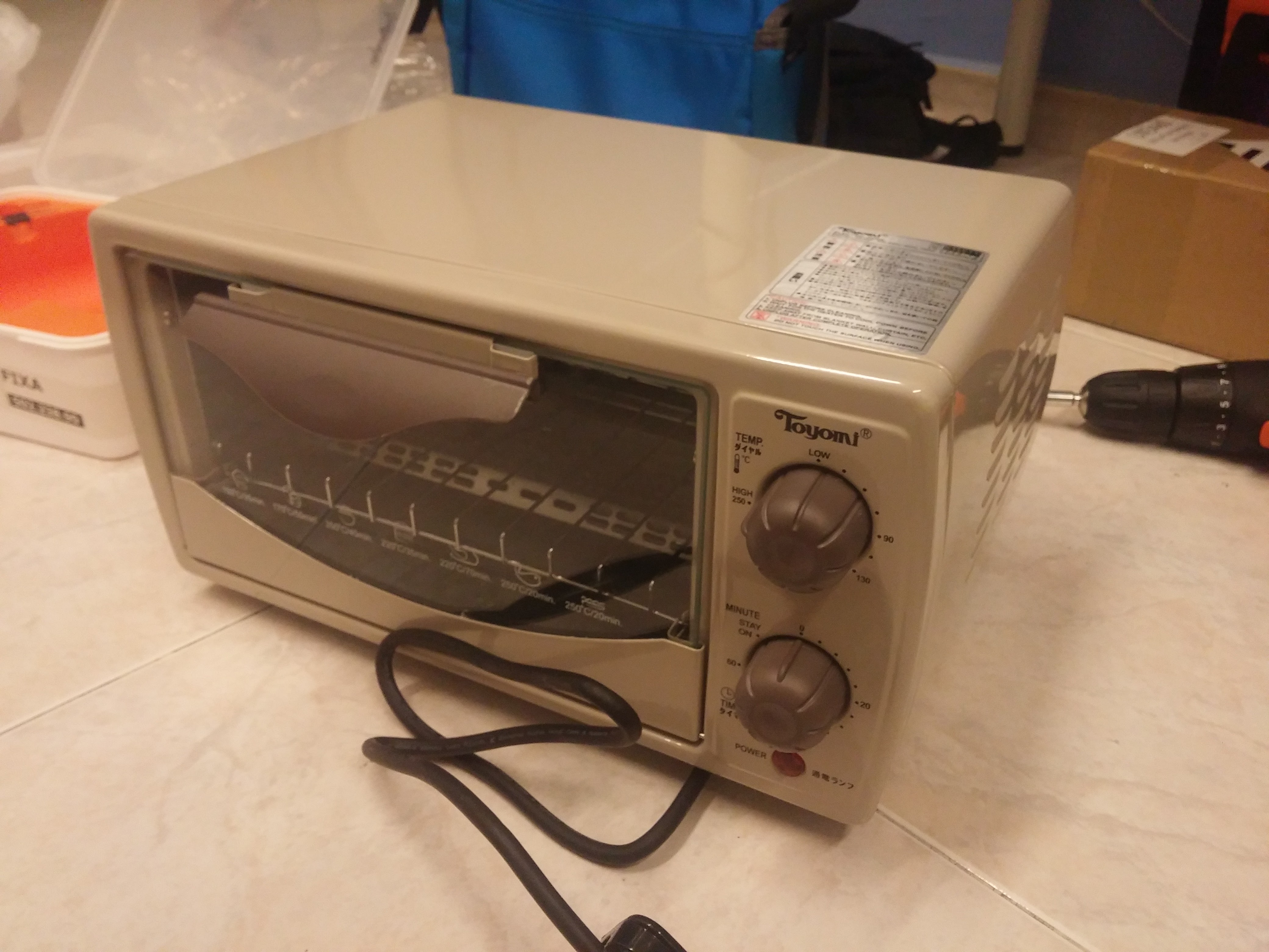
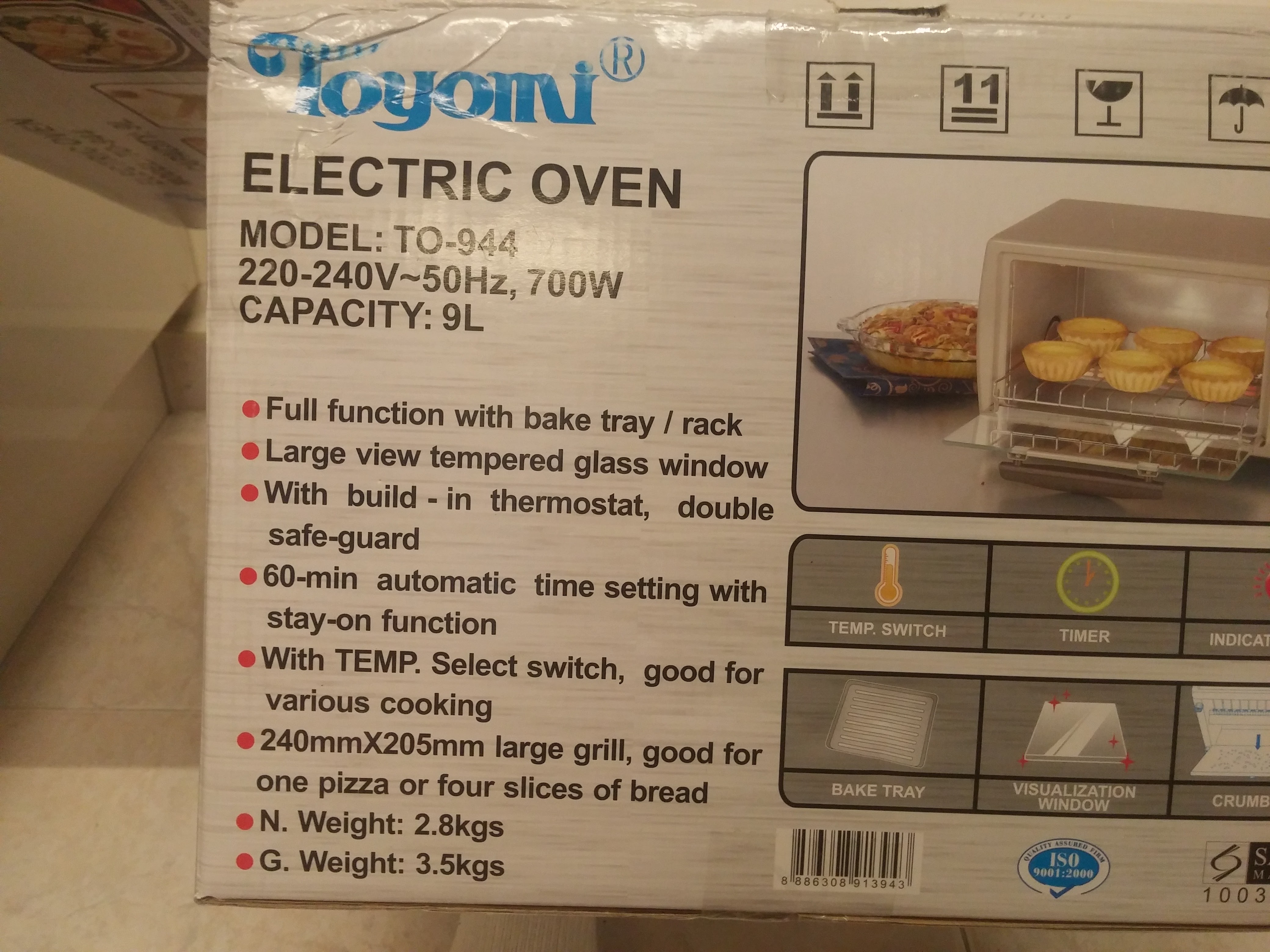
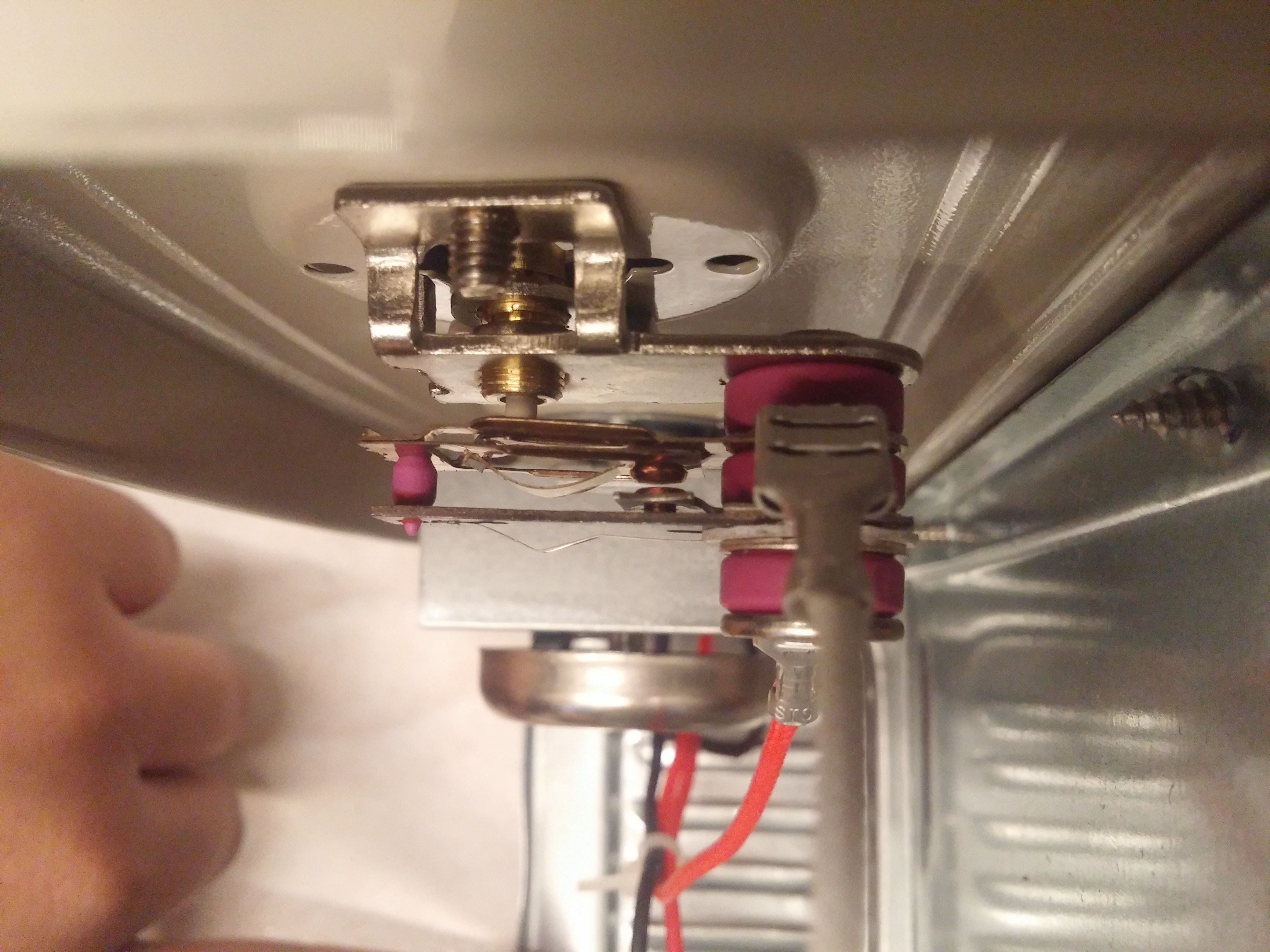
For its price, this toaster's not bad. It comes equipped with a bimetallic strip based thermostat design which is pretty commonplace in toasters these days. When the strip heats up to the right temperature, it bends away from the contact and disconnects the power to the heating element. Pretty neat low-cost mechanism.
It has a nice big cavity inside which will work wonderfully with our extra electronics inside. It looks like with the amount of space we have to work with, we could easily enclose everything within the frame itself making it look as stock as possible
Introduction
The Ediplane brought you a simple Intel Edison flight controller. Now, it is time to kick it up a notch. Meet EdiCopter, a full blown autonomous flight controller with many improvements and added features as compared to the EdiPlane Board.
Improved feature list
- STM32uf103 microcontroller (32 bit)
- 6 PWM Outputs
- Onboard power distribution( takes 3S/4S)
- More GPIO out for convenience
- MicroSD Card for logging
- 70mm x 37mm
Documentation
We are proud to say that this is the first open-source Intel Edison based flight controller. We will release the schematics and kicad files soon once we confirm its functionality. We will post a follow up to this with testing results once we manage to assemble the board.
Potential applications
This board could be used as a autonomous drone controller which is its primary goal. However, the GPIO breakouts allow you to customize the firmware to act as a general single board computer which has a multitude of applications in all kinds of systems f
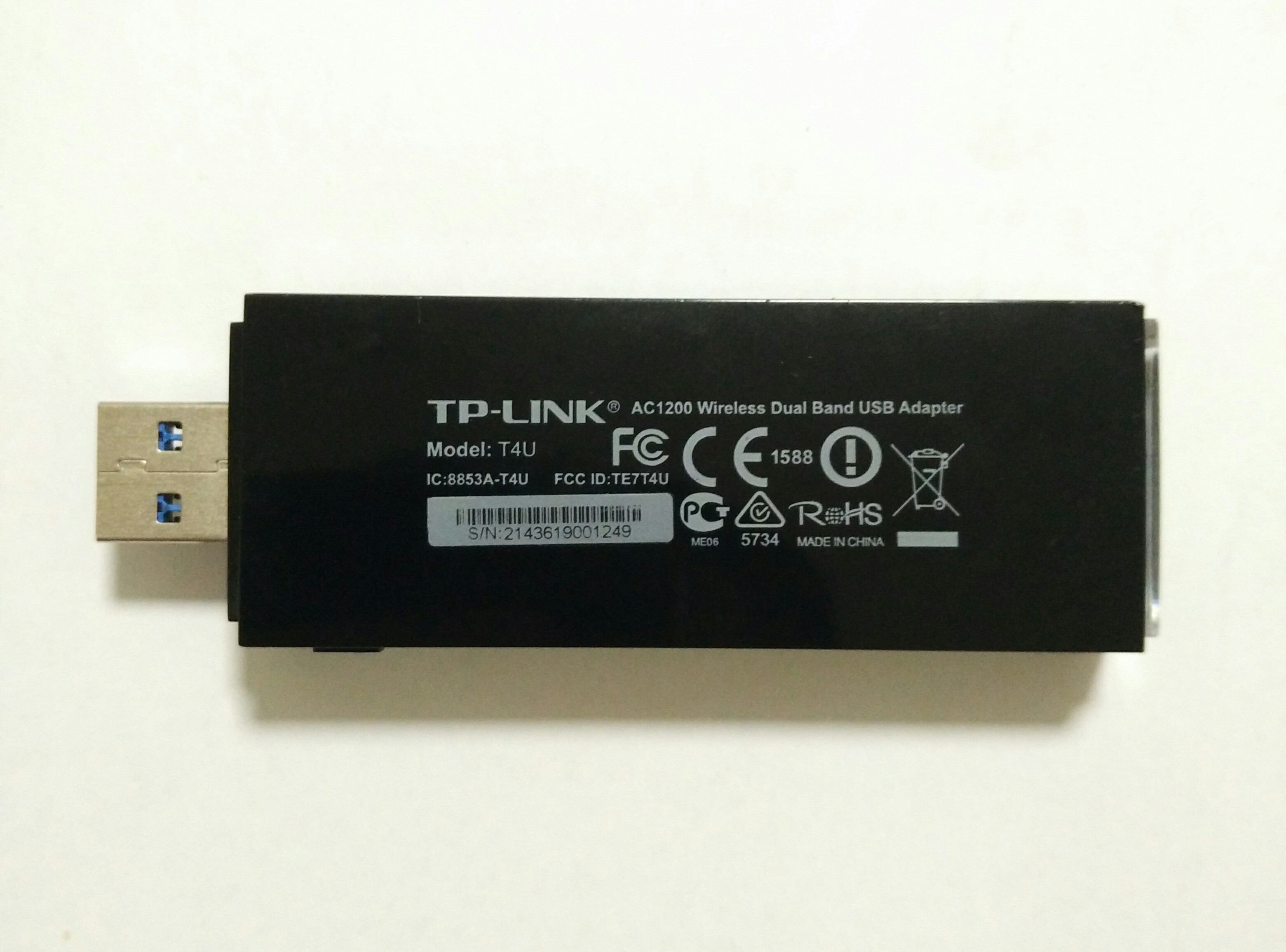
So, I went on Carousell and bought a Wireless USB card, being a poor guy with no income. The seller had used it quite a bit, but I was fine with second hand equipment. It came with a USB 3.0 extension cable, capable of 802.11ac at 867Mbps. And the WPS button on the side of the adapter made me cringe.
As usual, I decided to take it apart.
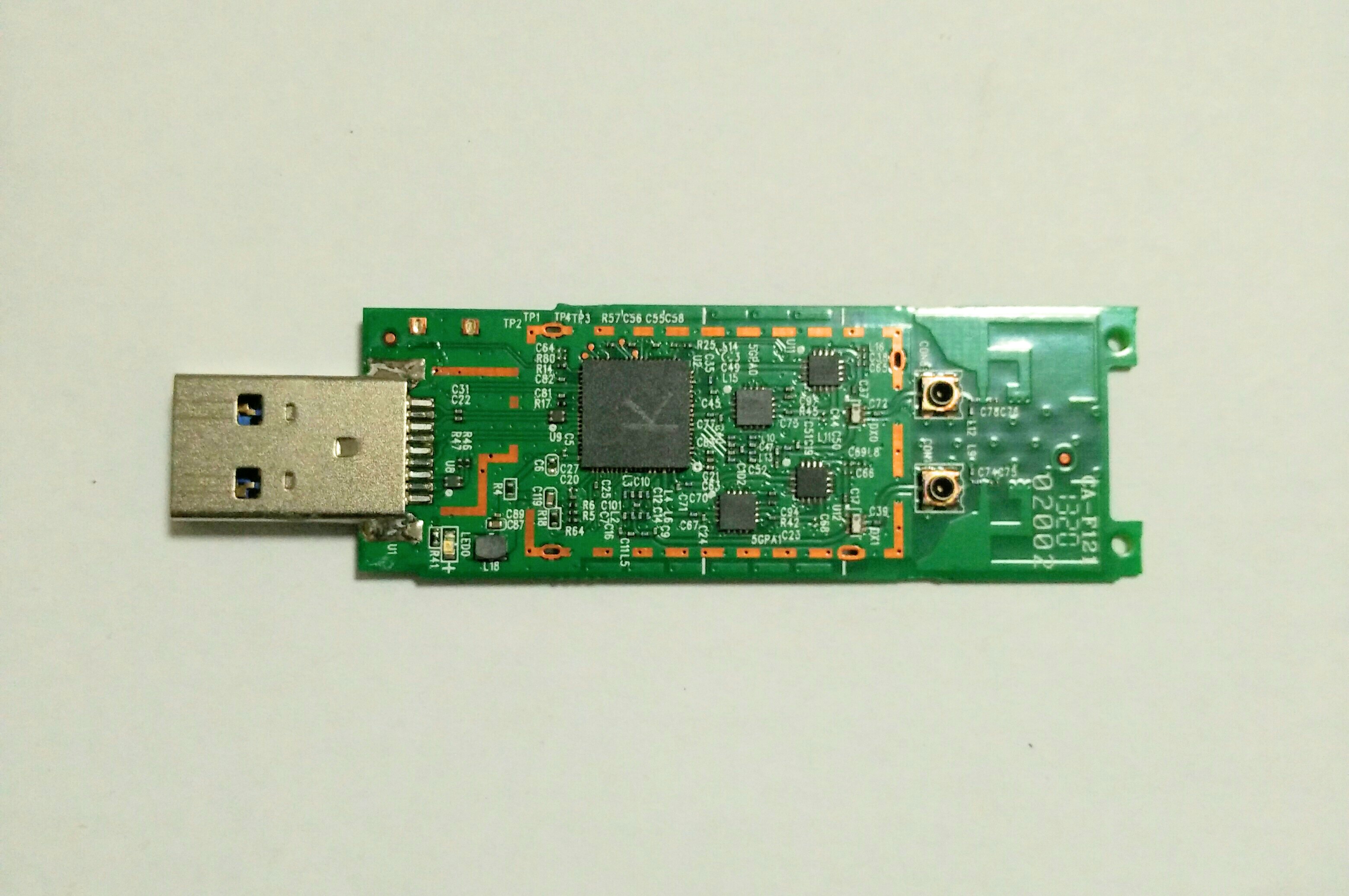
While I was researching on this adapter, I stumbled upon the WikiDevi page for this adapter (WikiDevi is a really cool site to find wireless equipment information, like routers and radio chipsets). It uses a Realtek RTL8812AU chipset.
Because I originally intended to find a dual band USB adapter for wireless sniffing, I went on to find Linux driver support for the RTL8812AU chipset. Because this chipset seems to be quite recently released, driver support information I found was contradictory, but the Gentoo wiki confirmed driver support. It's currently provided by two open source drivers, this one written from scratch and this one based on the Realte
Introduction
The quadcopter industry has been booming recently and along with that has come a surge of new flight controllers. Along with the popular APM and Naza platforms, flight controllers like the Naze 32 are also taking front stage. Recently, I decided to build an autonomous quad from scratch and I found myself stuck. I simply could not find a capable flight platform for a fully autonomous flight platform with a vision system. All the flight controllers today required some form of seperate computer like the Raspberry Pi to carry out vision robotics. So, I decided to do myself a favor and go make a fully autonomous quad platform.
The EdiPlane board
The EdiPlane board is Edison-Arduino integrated board which is intended for use in a fully autonomous drone/rover platform. It takes the ATMEL ATMEGA 328 chip and combines it with the computing power of the Intel Edison to get a perfect combination of computing power and I/O pins.
How it works
The EdiPlane is simply a board which allow