DIY solder reflow oven - software
Part 1: Toaster
Part 2: Electronics
Part 3: Software
Part 4: Conclusion
In this penultimate installment to the reflow oven project, we will wrap up by quickly going through some basics of the final hardware assembly and the software.
Insulation
Insulation is a important concern when you are building a reflow oven. If poor attention is given to insulation, you might end up reflowing your control electronics along with the other board. I implemented insulation by putting all the sensitive electronics into a cardboard box.
Power
Another important concern is the power for the arduino and the processing board. I implemented that by hacking a 5V 2A power supply and converting 240AV to 5VDC in the toaster. This 5VDC can then be used to power the electronics.
Software
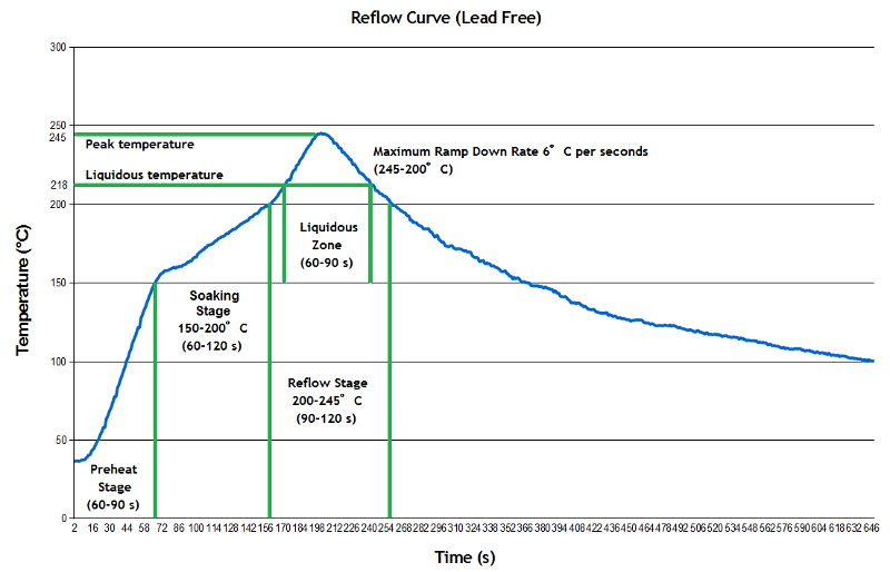
The software is critical to this project. Every reflow oven goes through 3 main phases. These phases are Preheat, Soak and Reflow. This is illustrated in the graph below. This is what is known as a reflow curve.
Since the computing platform we have is quite limited in power and because I am lazy, we went for a simple implementation for the the reflow curve. Instead of having an actual curve, we used simulated a piece-wise function instead composing of multiple linear units. This is first achieved by a simple algorithm which regulates the temperature.
// Temperature regulation
void regTemp(int temp) {
  int diff;
  diff = temp - set;
  if (diff < 0) {
    setStr("HEAT ON", 1, 20, BLACK);
    digitalWrite(relay, HIGH);
  }
  else if (diff > 0) {
    setStr("HEAT OFF", 1, 20, BLACK);
    digitalWrite(relay,LOW);
  }
}
There is also an interrput set to go off every second. Then using that as a timer, I am able to set the setpoint for the temperature regulator at specific intervals which allows me to set up a linear curve.
// Interrupt setup
void setup(){
//More code goes here
TCCR1A = 0; // CTC mode (interrupt after timer reaches OCR1A)
TCCR1B = _BV(WGM12) | _BV(CS10) | _BV(CS12); // CTC & clock div 1024
OCR1A = 15609; // 16mhz / 1024 / 15609 = 1 Hz
TIMSK1 = _BV(OCIE1A); // turn on interrupt
}

void loop(){
//More code goes here
}

SIGNAL(TIMER1_COMPA_vect) {
  // This function calls every second
}
Then I used a temperature setting passed to the regtemp() function by changing the global variable set. This setting is updating by counted the number of times the function SIGNAL(TIMER1_COMPA_vect) runs which should be once a second. You will then end up with something like this.
.
.
else if((90<timeCount)&&(timeCount<210)){
      setStr("Soak       ", 1, 40, BLACK);
      set=217;
    }
   else if((210<timeCount)&&(timeCount<240)){
     // Serial.print("hi");
      setStr("Reflow     ", 1, 40, BLACK);
      set=250;
   }
   else if((240<timeCount)&&(timeCount<270)){
      setStr("Reflow     ", 1, 40, BLACK);
      set=set-1;
   }
   else if(timeCount>270){
      setStr("Cool       ", 1, 40, BLACK);
      set=25;
   }
.
.
Problems
There was one huge problem with the way I implemented the code. My oven's thermal mass was a bit to high and it couldn't heat up or cool down fast up to have the ability to accurately follow the curve. To allow it to heat slower but still allow the board to experience an ideal reflow curve pattern, I added a preheat feature which allows you to heat up the oven to a certain temperature before starting the reflow process and putting your board in the oven. This solved the problem and the headstart it got by the preheat process is enough to keep it going straight through the reflow curve. The appropriate preheat code is below.
else if(timeCount==90){
    while(digitalRead(but)==HIGH){
        setStr("Place Board", 1, 40, BLACK);
        int c =(int) thermocouple.readCelsius();
        if(c!=0){
          String myString = "";
          myString += c;
          myString += " Celsius";
          char temp[50];
          myString.toCharArray(temp, 50);
          setStr(temp, 1, 10, BLACK);
          regTemp(c);
          updateDisplay();
          delay(100);
        }
In this example we used a 90sec preheat time but you can change it to anything you want.
Gitlab code
The full code is available here. You can clone straight into the repo. This is completely free with no licensing. Feel free to reuse it.
Conclusion
Before I close this project for good, I would like to say that a reflow oven is a really cool tool that any electronics hobbyist should consider making. And with such a tool being made for under 200SGD is quite a steal. I may post a follow up to this tutorial series by checking out and posting the performance review of the oven I made.