Building your own Linux OS from scratch is no dark magic, believe me! As long as you feel comfortable using a command line, it isn't such a daunting task, only requiring a fair amount of patience.
We'll be setting up an environment, compiling the kernel, userspace tools, a root filesystem and then test booting it. I'll assume you already run Linux on a machine, or in a Virtual Machine. Let's dive right in!
Environment
We'll first install the programs necessary for building. All these tools should be available in the major Linux distributions, but I'll only give the commands to install them on Debian/Ubuntu and Alpine Linux.
To compile the kernel, we need:
debian$ sudo apt install build-essential xz-utils libncurses5-dev bison flex bc perl libelf-dev libssl-dev  linux-headers-generic
alpine$ apk add apk add alpine-sdk xz ncurses-dev bison flex bc perl libelf-dev openssl-dev linux-headers findutils
Kernel
First we have to fetch the source.
$ KERNEL_VERSION=linux-4.18.6
$ wget https://cdn.kernel
Caddy is a easy-to-use web server and reverse proxy. You can use it to enable HTTPS on your self-hosted app with little effort.
To start off, first download caddy for your platform. Place the executable in a nice folder. We'll call that your working directory.
Now in the same folder, you will need to write a Caddyfile, which is just a text file. Open your text editor and paste this:
:2015 {
    proxy / localhost:8080
}
Save it as Caddyfile without any file extension.
This will start a normal HTTP server at port 2015 and proxy all requests to your app at port 8080.
Now, in the terminal or command prompt, cd into the working directory and run Caddy. On Windows you would type caddy.exe and on macOS or Linux ./caddy
You can now visit localhost:2015 to check that everything works.
Next, you have to get a domain to point to your server. You can get free domains from freenom.tk, or use your dynamic DNS provider. You can test that your domain works by visiting your-domain.com:2015 over mobile
Part 1: Toaster
Part 2: Electronics
Part 3: Software
Part 4: Conclusion
So it has been a while and I've been using the solder reflow oven for a while now. For the past weeks, I've been experimenting with finer and finer pitch components and I've been having really good progress so far.
The reflow oven performs way better than what I expected as it has fairly even heating through the oven and can solder super fine pitch components. One such example is the edison or hirose 70 pin connector. Despite the 0.5mm pin pitch my reflow oven managed to perfectly reflow the connector countless times.
So having said that, I think there are still a few software bugs that plagu
Part 1: Toaster
Part 2: Electronics
Part 3: Software
Part 4: Conclusion
In this penultimate installment to the reflow oven project, we will wrap up by quickly going through some basics of the final hardware assembly and the software.
Insulation
Insulation is a important concern when you are building a reflow oven. If poor attention is given to insulation, you might end up reflowing your control electronics along with the other board. I implemented insulation by putting all the sensitive electronics into a cardboard box.
![]()
Power
Another important concern is the power for the arduino and the processing board. I implemented that by hacking a 5V 2A power supply and converting 240AV to 5VDC in the toaster. This 5VDC can then be used to power the electronics.
Software
The software is critical to this project. Every reflow oven goes through 3 main phases. These phase
Part 1: Toaster
Part 2: Electronics
Part 3: Software
Part 4: Conclusion
In this second installment of the solder reflow oven series, I'll be going over the electronics that makes it work. The solder reflow oven can be split into 3 main sections.
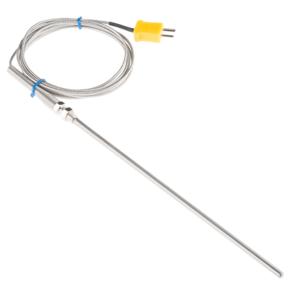
Temperature Detection
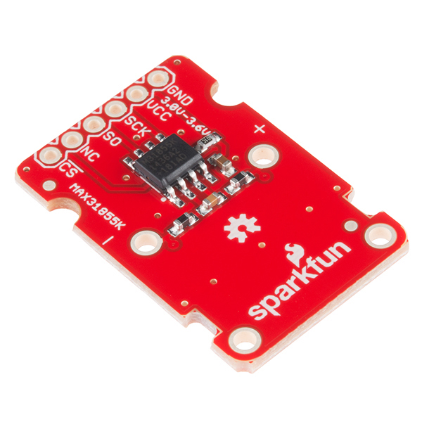
The first section is the temperature detection. The temperature detection at this kind of high temperatures (around 250°C) requires the use of a thermocouple to work. This is because a thermistor doesn't work at high temperatures. The thermocouple I obtained was from SparkFun and was a type K thermocouple. As a typical microcontroller cannot directly read the output of this thermocouple, it is necessary to have an external circuit to process the thermocouple voltages. Fortunately, SparkFun also sells a MAX31855K breakout board which I also grabbed.
Heating Element Control
The second section is the control method. To manipulate the temperature inside the oven, we need to toggle the power to the heating elements. For this,
So this will be the first post in a series of me making my own solder reflow oven. As you all know, the number of PCB related posts are increasing steadily with EdiCopter and our custom quadcopter boards on the way. I though that this would be the perfect time to get ourselves a solder reflow oven and maybe start small scale manufacture and went over to a nearby shop and grabbed myself the cheapest toaster money could buy.
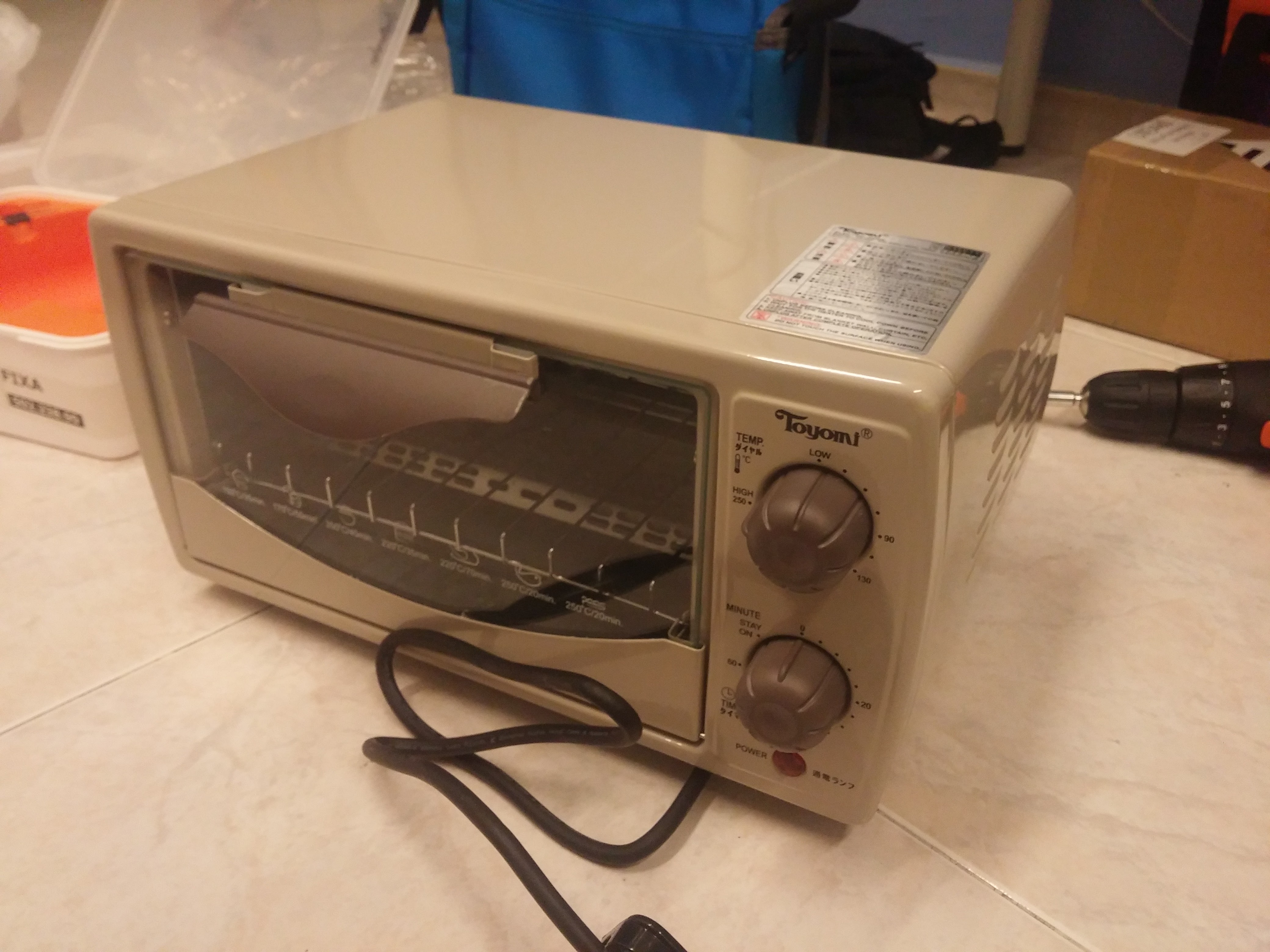
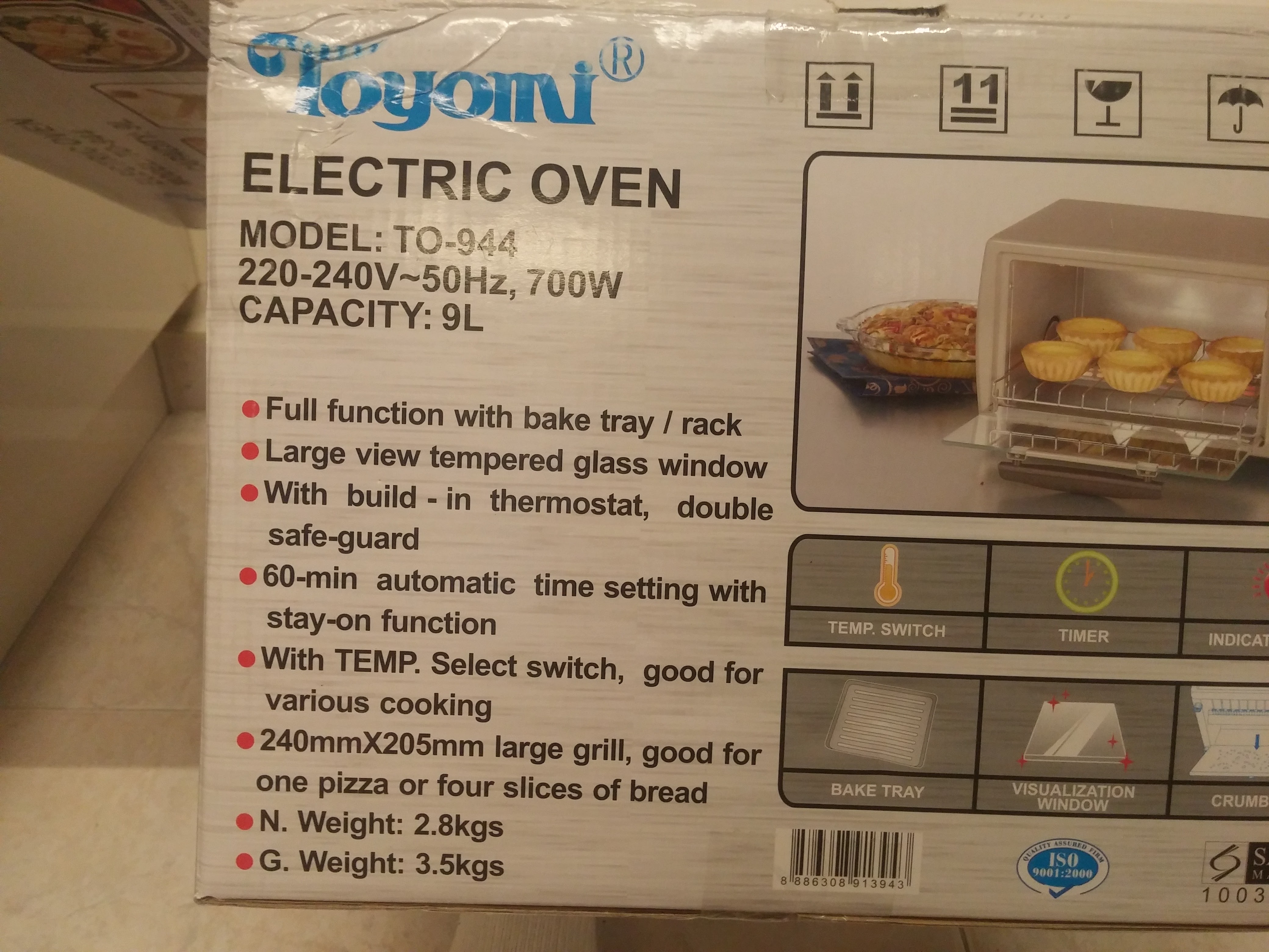
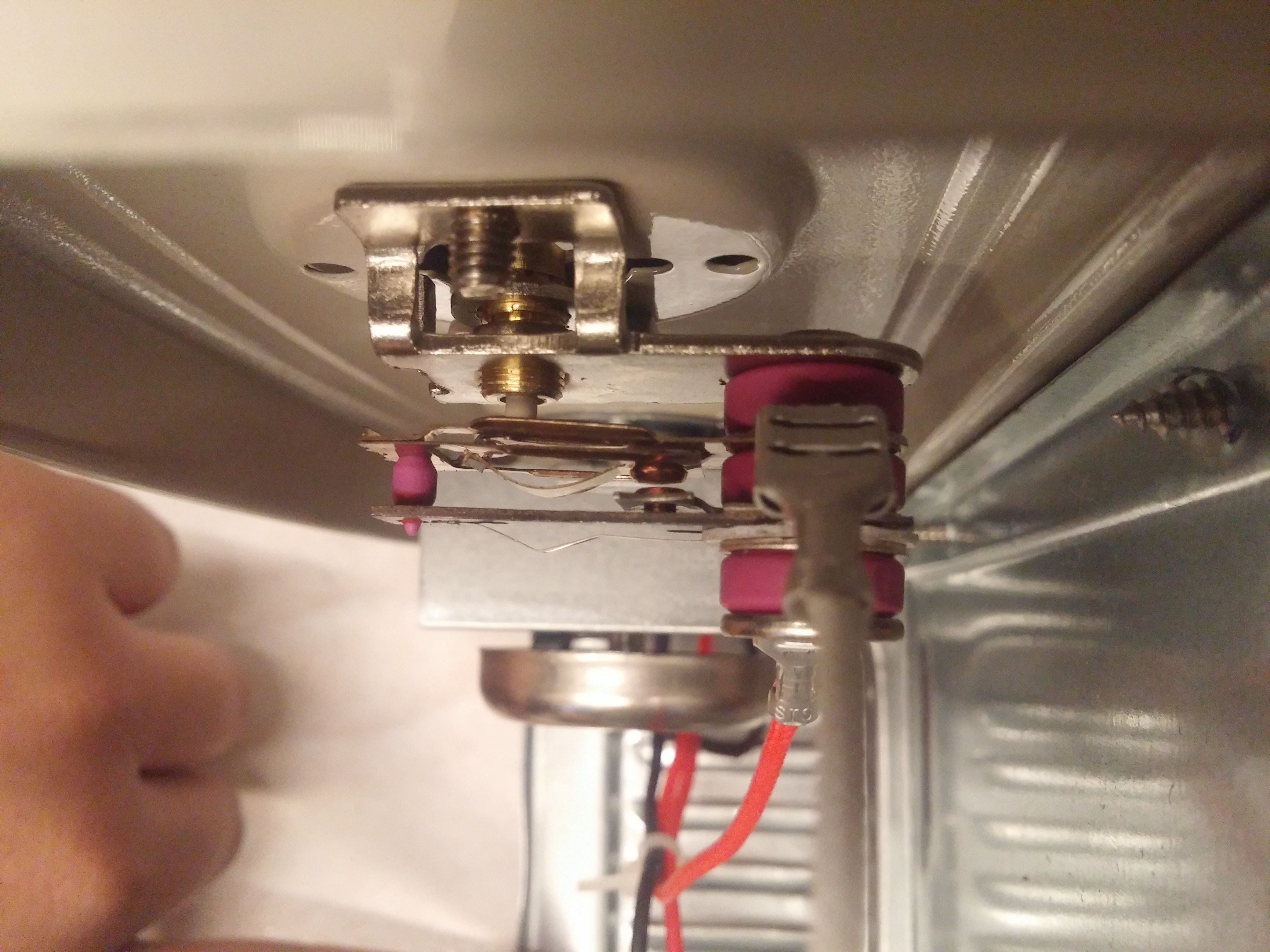
For its price, this toaster's not bad. It comes equipped with a bimetallic strip based thermostat design which is pretty commonplace in toasters these days. When the strip heats up to the right temperature, it bends away from the contact and disconnects the power to the heating element. Pretty neat low-cost mechanism.
It has a nice big cavity inside which will work wonderfully with our extra electronics inside. It looks like with the amount of space we have to work with, we could easily enclose everything within the frame itself making it look as stock as possible
PCB making in Singapore is a topic I've seen not many people talk about. Being one of the bustling cities in South East Asia one would expect to receive quality PCB making services locally in Singapore. On contrary, PCB making in my experience has not exactly been a honeymoon experience one would hope for. In this post, I will share my experience with making PCB's in Singapore and talk about the pros and cons of making PCB's locally.
Experience
I was trying to make a PCB for a school research project last year. More specifically, I was trying to make a Intel Edison based flight controller for a custom drone. Another post will be done detailing the PCB itself. Anyway, because along with the normal SMD connectors the Intel Edison connector cannot be soldered by hand, I required assembly services along with the conventional fabrication requirements.
Because of this limitation, I needed to build it locally to avoid incurring shipping costs and complications of sending the components overse