Room automation
This is the first installment in a series of posts which documents my journey into room automation. We have come up with a basic plan and bought essential materials which I will be outlining in this post. In the next post, I will be talking about the installation of the system, in the third post I will talking about the software be the project and in the last post I will conclude with a study on its feasibility and usefulness.
The Plan
My room is an average sized room with the normal functionality. I have 1 light, 1 fan and an air-conditioning unit which needs to be remotely controlled. I do have a desktop PC in my room which can potentially used as the controller unit. I also need a passcode lock security system to be implemented as my projects and expensive equipment are going to be stored in my room.
The current plan is to use the PC as the main controller and the Arduino Pro mini as the micro controller. The PC can send serial commands over wifi to the Pro Mini which is connected to the relays and the other sensors. As for the Wifi control, we will use the ESP8266 module to provide a interface to the computer. A more detailed material list is provided below.
Material List
- Sparkfun Pro Micro
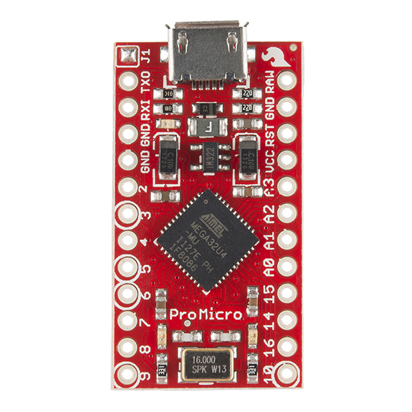
The brains of the home automation system-it controls and interfaces the sensors and actuators to the computer.
- Sparkfun BeefCake relays(2x)
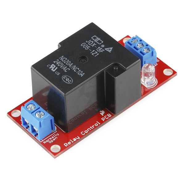
These are the muscles of the system able to handle 20A at 240VAC. These will be used to switch our AC appliances on and off.
- Sparkfun Electret microphone breakout
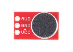
The electret microphone allows us to add the clap on and off functionality for the lights in the room.
- ESP8266
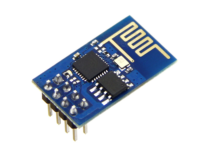
This acts as the interface between the pro micro and the computer allows both of them to communicate to one another without any wires
- Logic level converter
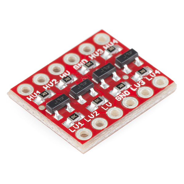
This allows the ESP8266 to interface with the Pro mini
- IR transmitter
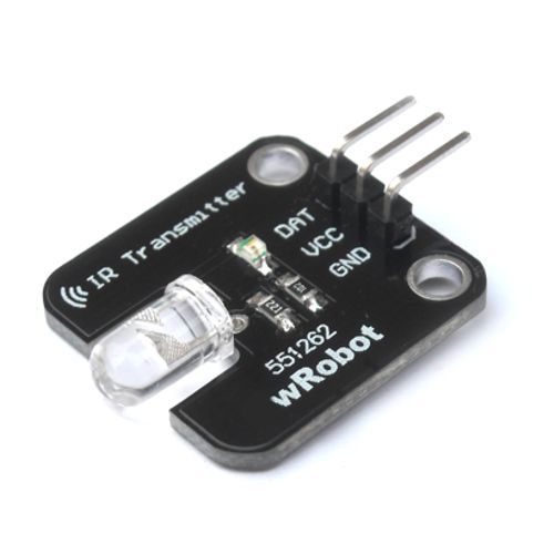
This allows for us to control remote appliances via IR when necessary
Parts of the system
This section will go through the essential parts of the system and how they work together.
Door Lock
The door lock system uses a 3D printed rack and pinion system provided from thingiverse found here. This will be connected to a 10kg hitec servo which will actuate to pinion to act as a deadbolt. The PWM of the servo will be controlled by the digital pin on the Pro Mini and will be covered in more detail in the next post.
The door lock is controlled via the keypad places on the wall outside the room which is routed into the Pro Mini through a hole in the wall.
Clap to wake
The double clap to wake system will be controlled by the electret microphone which will be coded to detect spikes in audio over a certain threshold which then triggers the activation of the lights and the fan. Another double clap while on will cause the room to turn off the lights and fan.
Computer interface
The computer interface gives the system remote access as the computer is connected to the internet and can act as a server. This allows me to control the room from anywhere as long as there is internet connection as the pro micro is connected to the computer a UART connection.
MakerComm system
MakerComm is an additional system that will be implemented in later posts which allows for voice control of the room and allows for MakerComm to act as our personal asssistant.
Conclusion
In the next post, we will cover the installation of the system and in the following post we will go over the software aspects of the system as well.